Fixing DVI input of my HP monitor
I used to use my monitor, a HP L2245w, only by using its VGA input because it was the only cable I had lying around. But some time ago, I had a project that required to use its DVI port and I bought the cable.
When hooking my PC to the monitor via DVI for the first time, I noticed that the resolution was really bad: 1024x768 was used even though my monitor supports 1680x1050 and it wasn’t possible to select higher resolutions using xrandr without creating a custom profile. The same effects could be observed on Windows and also my UEFI splashscreen was broken.
After trying with different cables and different PC setups, I figured out that the problem came from the screen. At that time, I didn’t really know whether the problem was electrical or some sort of firmware issue but my inital guess was that a random thing related to DVI on the PCB blew up.
I decided to investigate on the software side first anyway (and I was right).
A bad EDID story⌗
After some time, I had the idea to look into dmesg and I found a bunch of theses messages :
i915 0000:00:02.0: HDMI-A-1: EDID is invalid:
	[00] BAD  00 00 00 a0 00 ff ff 00 22 f0 fc 26 01 01 01 01
	[00] BAD  18 12 01 03 80 2f 1e 78 ee b1 30 a5 56 4a 9a 25
	[00] BAD  11 50 54 a5 6b f0 81 40 81 80 95 00 a9 00 b3 00
	[00] BAD  01 01 01 01 01 01 21 39 90 30 62 1a 27 40 68 b0
	[00] BAD  36 00 d9 28 11 00 00 1c 00 00 00 fd 00 32 4c 18
	[00] BAD  53 11 00 0a 20 20 20 20 20 20 00 00 00 fc 00 48
	[00] BAD  50 20 4c 32 32 34 35 77 0a 20 20 20 00 00 00 ff
	[00] BAD  00 43 5a 4b 38 32 34 30 34 32 4e 0a 20 20 00 7f
Special thanks to the i915 Linux driver developers that implemented proper debug messages for this case. FYI the proprietary nvidia Linux driver doesn’t have these. I bet nobody is surprised.
EDID is a standard adopted by the whole industry making digital monitors. Basically, any compliant peripheral delivers a payload to the video card that contains its capabilities in terms of color, format, resolutions etc. Thanks to that, your video card knows which is the resolution and the color profile it can use for your screen.
Back to the problem, it seemed that for some reason my monitor sends a bad EDID payload. I tried to disconnect/reconnect the screen multiple times and noticed that the wrong EDID payload was the same each time. The corruption of the EDID message wasn’t random or happening at plugin time. Good.
But after all, what was wrong with the EDID payload sent by my screen. Was it random garbage or just a corruption in some bits ? To know that, I compared the EDID payload format specified by the standard and the payload showed by the i915 message. It did not take me long to find a corruption. The standard specifies that the EDID payload begins with the following magic value: 00 ff ff ff ff ff ff 00, and as you can see from the debug message, 4 of these 8 bytes don’t match. Weird.
A little detour by the service mode⌗
As I had no clue of why this corruption happened, I thought that maybe there was somewhere a hidden parameter that would allow me to fix the EDID. Obviously, such a parameter wouldn’t be available in the regular settings panel so I began to look for the service or factory mode of my screen.
As expected, it was not easy to find how to enter service mode but after some research, I found my way in. I leave the complete procedure as an exercise to the reader :)
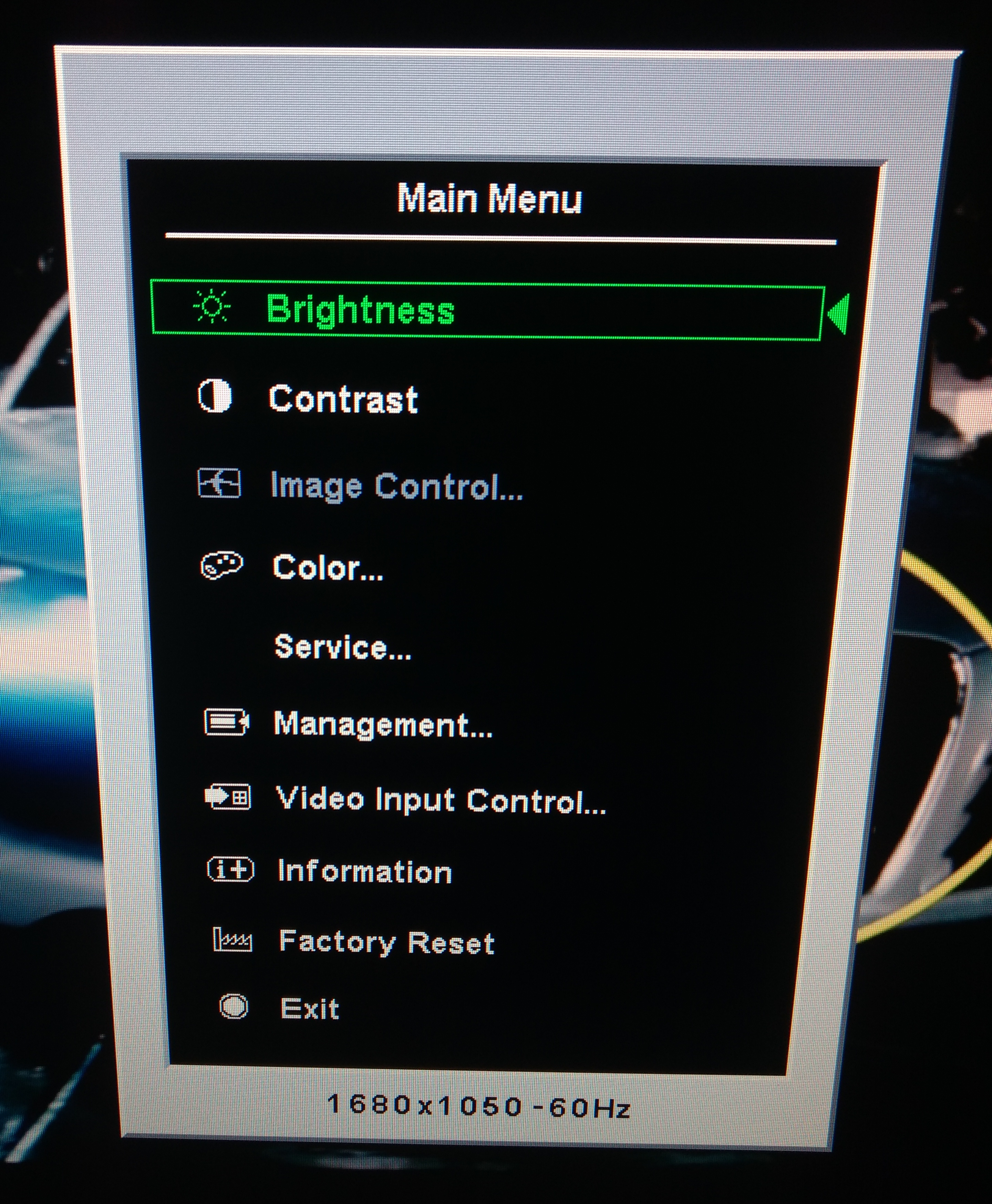
The cursor is now green instead of yellow and a new menu option appeared: Service. When you enter this menu, you see the following options:
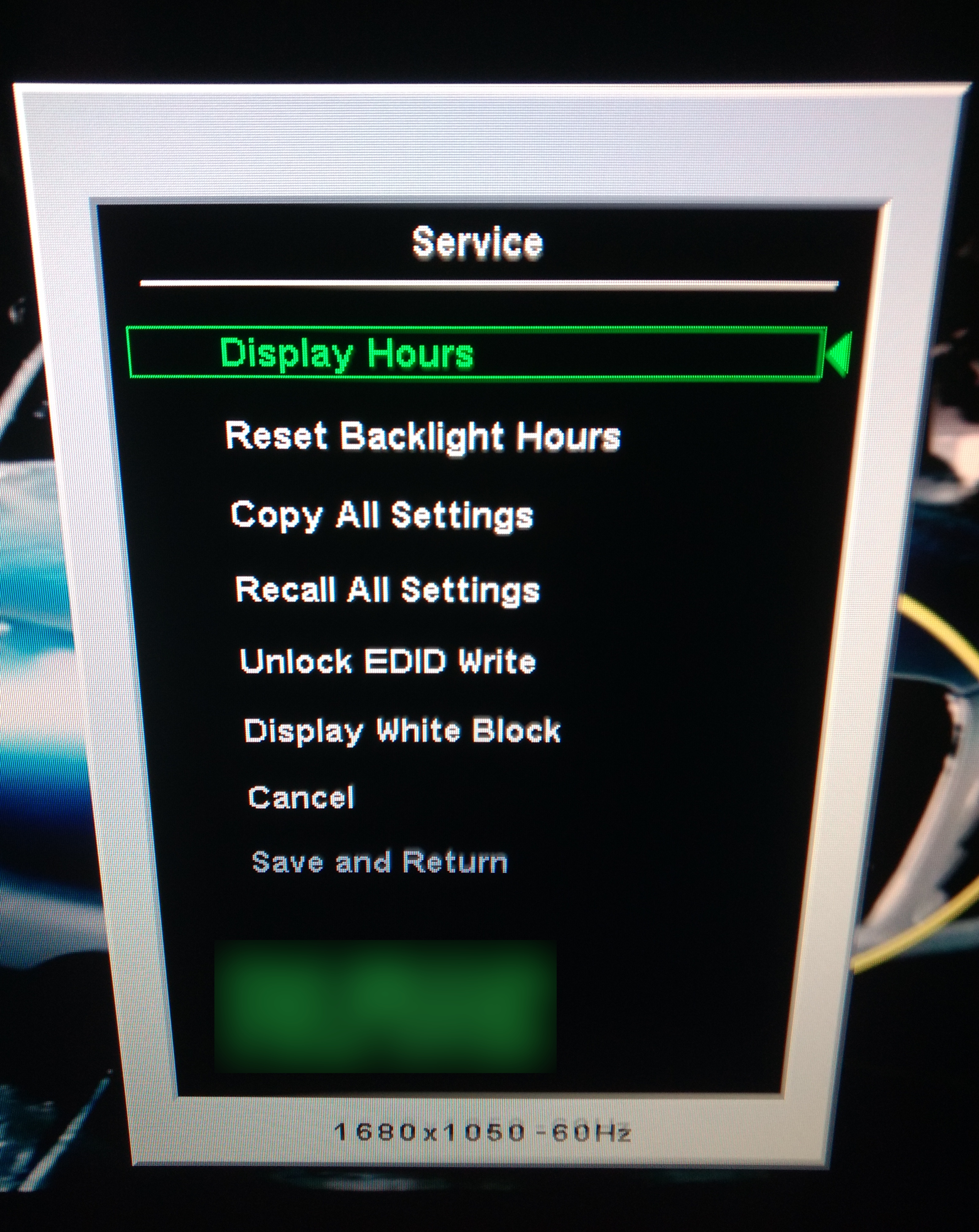
All these options are pretty boring except the Unlock EDID Write one. Of course I want to unlock EDID write! So I enabled it but there was nothing in the interface itself that would indicate me how I write the EDID memory.
Writing the EDID on the monitor’s EEPROM⌗
Luckily, I stumbbled across this video from yzarc314 that had a problem of screen image offset when he uses a DVI-HDMI cable on his LG screen, which was due to missing fields in the EDID of his monitor. He/she uses the I2C bus provided by HDMI (which is used for display-host communication as per HDMI spec) to reprogam the memory holding the EDID information on his display.
After all, as pointed out on this thread on StackExchange, it makes a ton of sense to wire directly the I2C bus of an EEPROM holding the EDID info directly onto the I2C pins of the DVI/HDMI, that way it makes it really easy to program the EEPROM.
So I made the assumption that his method was going to work on my HP screen and began to follow his procedure that I’ll detail here for the sake of completeness.
- Load the
i2c-devmodule on your kernel:modprobe i2c-dev - Install the I2C tools for your distribution, for archlinux the package is named
i2c-tools - Find the I2C bus number of your DVI/HDMI port connected to your screen. You can list all of them using the command
i2cdetect -l. Try only those related to your graphics chip, in the example below only the ones mentioningi915. Another important advice would be to have only one monitor connected to your PC, the one you want to debug, to avoid mistakes.
florian:~/ $ sudo i2cdetect -l
i2c-3	i2c       	DPDDC-A                         	I2C adapter
i2c-1	i2c       	i915 gmbus dpb                  	I2C adapter
i2c-4	i2c       	DPDDC-D                         	I2C adapter
i2c-2	i2c       	i915 gmbus dpd                  	I2C adapter
i2c-0	i2c       	i915 gmbus dpc                  	I2C adapter
i2c-5	smbus     	SMBus I801 adapter at f040      	SMBus adapter
- To verify that you are using the right bus, issue
i2cdump <bus_no> 0x50and you should see an output like the one below that should correspond to the EDID data stored on the EEPROM. Note that0x50is the address to query on the SPI bus, it may vary from one device to another but it seems fairly common because I used the same as yzarc314 and it worked.
florian:~/ $ sudo i2cdump 0 0x50
0 1 2 3 4 5 6 7 8 9 a b c d e f 0123456789abcdef
00: 00 ff 00 a0 00 ff ff 00 22 f0 fc 26 01 01 01 01 ...?...."??&????
10: 18 12 01 03 80 2f 1e 78 ee b1 30 a5 56 4a 9a 25 ?????/?x??0?VJ?%
20: 11 50 54 a5 6b f0 81 40 81 80 95 00 a9 00 b3 00 ?PT?k??@???.?.?.
30: 01 01 01 01 01 01 21 39 90 30 62 1a 27 40 68 b0 ??????!9?0b?'@h?
40: 36 00 d9 28 11 00 00 1c 00 00 00 fd 00 32 4c 18 6.?(?..?...?.2L?
50: 53 11 00 0a 20 20 20 20 20 20 00 00 00 fc 00 48 S?.? ...?.H
60: 50 20 4c 32 32 34 35 77 0a 20 20 20 00 00 00 ff P L2245w? ....
70: 00 ca fe ba be ff de ad be ef ff 0a 20 20 00 7f .Êþº¾ÿÞ¾ïÿ? .?
80: ff ff ff ff ff ff ff ff ff ff ff ff ff ff ff ff ................
90: ff ff ff ff ff ff ff ff ff ff ff ff ff ff ff ff ................
a0: ff ff ff ff ff ff ff ff ff ff ff ff ff ff ff ff ................
b0: ff ff ff ff ff ff ff ff ff ff ff ff ff ff ff ff ................
c0: ff ff ff ff ff ff ff ff ff ff ff ff ff ff ff ff ................
d0: ff ff ff ff ff ff ff ff ff ff ff ff ff ff ff ff ................
e0: ff ff ff ff ff ff ff ff ff ff ff ff ff ff ff ff ................
f0: ff ff ff ff ff ff ff ff ff ff ff ff ff ff ff ff ................
As expected, the EDID data stored in my EEPROM was somehow corrupted, at least the first 4 bytes. I needed to replace these bytes by their correct value.
- First save the values before touching them:
i2cdump 0 0x50 > l2245w.edid - Write one by one the bytes you want to change
i2cset 1 0x50 <offset> <value> b. In my case, I issued the following commands:
sudo i2cset 0 0x50 0x04 0xff b
sudo i2cset 0 0x50 0x03 0xff b
sudo i2cset 0 0x50 0x02 0xff b
sudo i2cset 0 0x50 0x01 0xff b
After disconnecting/reconnecting the monitor, the problem was solved and the native resolution was used automatically. Mission accomplished!
To this day, I still have no clue about why the corruption happened in the EEPROM.